
Views: 278 Author: 广宇大 Publish Time: 2026-11-03 Origin: Site


Content Menu
● What Is a Linear Profile Spraying Machine?
>> Definition and Core Function
● What Is a Robotic Spray System?
>> Definition and Core Function
● Linear vs. Robotic: The Core Difference
>> How a Linear Profile Spraying Machine Works
>> How a Robotic Spray System Works
● Coverage Control for Complex Moulded Components
>> Why Complex Mouldings Are Difficult
>> How Linear Systems Handle Coverage
>> How Robotic Systems Handle Coverage
● Film Build, Overspray, and Transfer Efficiency
>> Overspray and Material Consumption
● Production Speed and Line Balancing
● Coating Types and Process Compatibility
>> Water-Based and Solvent-Based Coatings
● Ventilation, Safety, and Fire Prevention
>> Why Spray Booths Are Essential
● A Practical Selection Framework
>> Choose a Linear Profile Spraying Machine When:
>> Choose a Robotic Spray System When:
>> Consider a Hybrid Approach When:
● A Practical Validation Roadmap
>> Step 1: Define the Product Family
>> Step 2: Run a Coating Trial
>> Step 3: Validate the Complete Line
>> Step 4: Train Operators and Technicians
>> Step 5: Standardize Recipes and Maintenance
● Common Problems and Expert Solutions
>> Uneven Coating on Moulded Components
>> Overspray and Filter Loading
>> Color Variation Between Batches
>> Daily Checks
● How GYDFinishing Approaches Moulded-Component Finishing
>> What is the main difference between a linear profile spraying machine and a robotic spray system?
>> Which system is better for complex moulded components?
>> Can both systems apply water-based coatings?
>> Which system produces less overspray?
>> How should I compare production speed?
>> Can a factory use both systems?
Choosing between a linear profile spraying machine and a robotic spray system for complex moulded components depends on part geometry, production volume, coating process, changeover frequency, and the level of surface consistency your customers require. A linear system emphasizes continuous part flow and repeatable multi-gun coverage. A robotic system emphasizes flexible tool paths and access to complex three-dimensional surfaces.
From an equipment manufacturer's perspective, the decision should not be based on which technology sounds more advanced. For moulded doors, furniture components, cabinet profiles, decorative trim, and architectural mouldings, the decisive factors are coverage completeness, film-build control, overspray reduction, fixture design, changeover time, and accepted finished parts per shift.
This guide compares both systems from a practical production standpoint. It explains how each works, where each performs best, and how to validate the right solution for your actual moulded components.
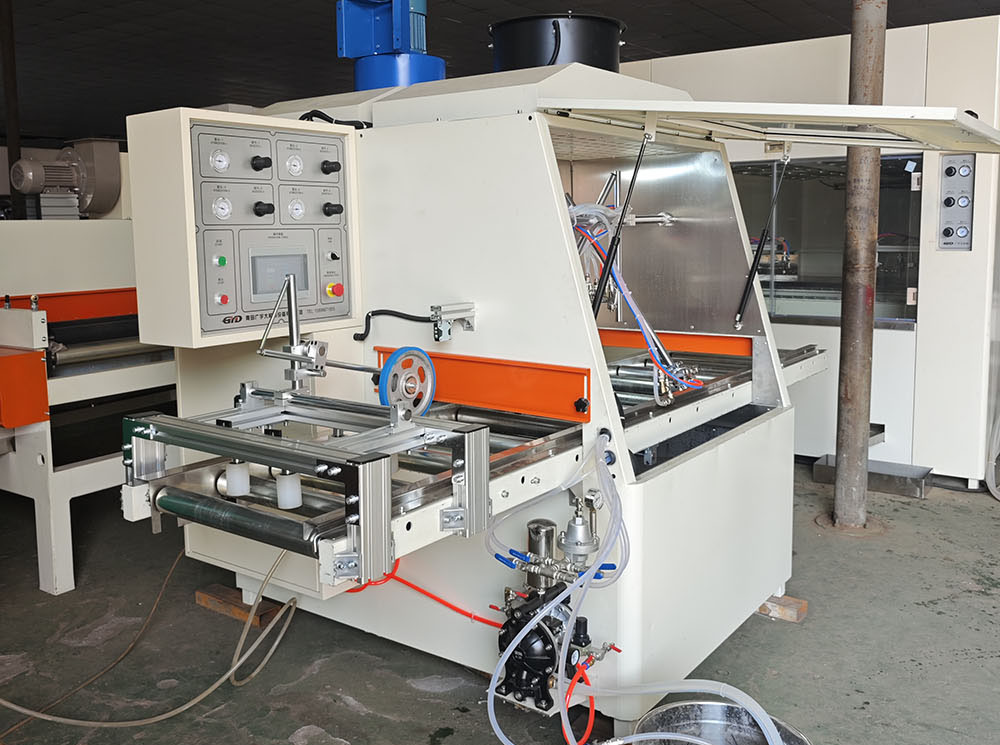
A linear profile spraying machine moves workpieces continuously through one or more spray stations. The workpiece travels on a conveyor, chain, rail, or roller system while spray guns apply coating from fixed, oscillating, or angled positions.
The machine may apply primer, sealer, stain, lacquer, topcoat, or protective clear coating. Gun activation, spray pattern, gun distance, fluid output, and line speed are controlled to achieve the required finish.
Key point: A linear profile spraying machine is not just a spray gun on a conveyor. It is an integrated process involving part transport, coating delivery, atomization, overspray capture, ventilation, and often drying or curing.
Linear profile spraying machines are widely used for:
- Door frames and architraves
- Cabinet door edges and frames
- Mouldings and decorative trim
- Flooring profiles and skirting boards
- Furniture rails and slats
- Window and door components
- Flat panels and linear workpieces
They are most effective when the product family is repeatable and the required finish can be defined clearly.
A robotic spray system uses one or more robotic arms to move spray guns along programmed paths around the workpiece. The robot can approach the part from multiple angles, follow curved surfaces, and reach recesses that fixed guns may not access.
The system may include a rotating fixture, conveyor, vision system, part-detection sensors, and recipe management. The robot follows a programmed tool path while the coating system controls fluid output, atomization, and spray pattern.
Key point: A robot does not automatically guarantee better quality. It provides flexibility and repeatability only when the part fixture, tool path, coating settings, and maintenance are controlled.
Robotic spray systems are commonly used for:
- Complex moulded furniture components
- Decorative architectural mouldings
- Cabinet door frames with deep profiles
- Three-dimensional panels
- Curved or irregular components
- High-value custom products
- Parts requiring multi-angle coverage
They are particularly useful when the part geometry changes significantly or when a single spray gun must reach multiple surfaces.
The fundamental difference is how the spray gun reaches the workpiece.
- In a linear profile spraying machine, the workpiece moves through a fixed spray zone. Coating coverage is largely determined by gun configuration, line speed, and spray activation.
- In a robotic spray system, the robot moves the spray gun around the workpiece. Coating coverage is determined by the programmed tool path, gun angle, standoff distance, and spray overlap.
Both systems can be automated. Both can be highly repeatable. The better choice depends on the component geometry, coating, and production objective.
A typical linear system follows this flow:
1. Load the moulded component onto the conveyor or fixture.
2. Detect the part using a sensor or operator input.
3. Select the coating recipe.
4. Move the component through the spray zone.
5. Activate the spray guns only when a part is present.
6. Apply the coating while the component moves forward.
7. Capture overspray through the booth exhaust and filters.
8. Send the coated component to flash-off, drying, or the next station.
The most important variables are gun distance, spray angle, fan pattern, fluid output, atomizing air, gun speed, line speed, and number of passes.
A typical robotic system follows a similar flow, but adds programmed gun movement:
1. Load the moulded component onto a fixture or rotating table.
2. Detect the part and identify the correct program.
3. Start the robotic spray path.
4. Move the spray gun around the component at controlled angles and distances.
5. Apply overlapping spray passes to cover complex surfaces.
6. Synchronize robot movement with coating flow and part rotation.
7. Capture overspray through the booth exhaust and filters.
8. Send the coated component to flash-off, drying, or the next station.
The most important variables are robot path, gun angle, standoff distance, spray overlap, fluid output, atomizing air, robot speed, and number of passes.
Complex moulded components often include beads, flutes, grooves, chamfers, curves, and deep recesses.
These features receive coating differently from flat surfaces. A spray pattern that works well on a flat board may leave dry spots in grooves or cause excessive build on raised edges.
Linear systems handle coverage through gun configuration and line-speed control.
Common gun configurations include:
- Top spray guns for upper surfaces
- Side spray guns for vertical faces
- Angled guns for chamfers and bevels
- Oscillating guns for variable widths
- Multiple spray stations for primer, sealer, and topcoat
- Rotating fixtures for profiles with multiple faces
For repeatable moulding families, a linear machine can provide excellent consistency. For highly complex or variable components, it may require additional guns, fixtures, or spray stations.
Robotic systems handle coverage through programmed tool paths.
The robot can adjust gun angle and distance to reach:
- Vertical faces
- Chamfered edges
- Grooves
- Beads
- Recessed areas
- Curved surfaces
- Multiple sides of a three-dimensional component
This can reduce the number of fixed guns required. It can also improve coverage on components whose geometry changes across the surface.
Expert insight: For complex moulded components, the best test is not a flat sample board. Always validate the process with the deepest groove, sharpest edge, and most difficult geometry in your actual product range.
Film build is the thickness of coating applied to the component. It affects appearance, durability, drying time, and downstream sanding.
In a linear system, film build is influenced by:
- Line speed
- Fluid output
- Number of spray passes
- Gun distance
- Spray angle
- Coating viscosity
In a robotic system, film build is also influenced by:
- Robot path
- Gun angle
- Standoff distance
- Spray overlap
- Robot speed
- Number of passes
- Synchronization with part rotation
The correct approach is to establish a validated process window: a range of settings that consistently produces acceptable results.
Overspray is coating material that misses the workpiece. It increases material consumption, contaminates the booth, increases filter loading, and creates more cleaning work.
In moulded-component spraying, overspray can be especially significant because the spray must reach edges, grooves, and recesses.
Linear systems can reduce overspray by using narrowly focused spray patterns and activating guns only when a part is present. Robotic systems can reduce overspray by matching gun angle, distance, and path speed to the component geometry.
Expert insight: The lowest-cost system is not always the one with the lowest purchase price. A machine that wastes less coating, produces fewer rejects, and requires less cleaning may deliver a lower total cost of ownership.
Linear systems are often preferred for continuous production because components move through the line without stopping.
However, advertised conveyor speed is not the same as accepted production output. You must also consider:
- Loading and unloading time
- Coating preparation
- Gun cleaning
- Color changes
- Filter replacement
- Drying or curing time
- Inspection and rework
A fast spray station cannot compensate for a slow curing stage or frequent maintenance stops.
Robotic systems may require more time per part if the robot must follow a complex path or complete multiple passes. However, they can be faster overall when they reduce the need for multiple spray stations or manual touch-up.
The useful comparison is not robot speed alone. Compare accepted finished parts per shift under the same product mix, coating, and quality standard.
Linear systems are highly effective for stable product families. They can store recipes for different profiles, coatings, and line speeds.
Changeover may involve:
- Adjusting conveyor guides
- Changing gun positions
- Selecting a new recipe
- Adjusting gun distance or spray angle
- Changing coating viscosity settings
For products with similar geometry, changeover can be quick. For very different profiles, it may require more mechanical adjustment.
Robotic systems can be more flexible when component geometry varies. The robot can follow different programmed paths for different parts.
Changeover may involve:
- Selecting a new robot program
- Changing fixtures or clamping method
- Adjusting gun angle or standoff distance
- Changing spray overlap
- Selecting a new coating recipe
- Verifying part detection and safety zones
For a factory producing many component variants, robotics can reduce the need for separate fixed-gun setups.
Both linear and robotic systems can apply:
- Water-based primers and topcoats
- Solvent-based lacquers
- UV-curable coatings
- Stains and glazes
- Sealers
- Protective clear coats
Each coating has different viscosity, drying behavior, transfer efficiency, and cleaning requirements.
Water-based coatings often require controlled temperature and airflow during drying. They are generally easier to clean up, but equipment compatibility must still be verified.
Solvent-based coatings may flash off faster depending on the formulation. They require compatible hoses, seals, pumps, and solvent-based cleaning procedures.
Important: "Water-based" does not mean "no ventilation required." OSHA notes that the need for spray booth ventilation depends on the presence of hazardous chemicals in the coating, not simply whether the coating is water-based. [2299]
Spray finishing can release mists, vapors, and residues. OSHA states that spray booths serve two main purposes: protecting worker health and reducing fire and explosion hazards. [2300]
A spray booth is a power-ventilated structure that encloses or accommodates a spraying operation to confine and limit the escape of spray, vapor, and residue and safely direct them to an exhaust system. [2309]
OSHA requires mechanical ventilation in spraying areas to remove flammable vapors, mists, or powders to a safe location and to confine and control combustible residues. [1720]
Ventilation must remain in operation during spraying and for a sufficient time afterward to exhaust vapors from drying coated articles and finishing-material residue. [1720]
OSHA also states that the total air volume exhausted through a spray booth should dilute solvent vapor to at least 25 percent of the lower explosive limit of the solvent being sprayed. [2297]
Both linear and robotic spray systems should include:
- Properly designed spray booth or enclosed spray zone
- Mechanical exhaust ventilation
- Make-up air supply
- Filter maintenance program
- Grounding and bonding for static control
- Appropriate electrical classification where required
- Coating storage and handling controls
- Operator training
- Emergency stop and interlock systems
- Regular inspection of hoses, pumps, guns, and filters
Do not treat ventilation as an optional accessory. It is a core safety and quality system.
- Your components are linear, repeatable, and similar in geometry.
- You need continuous high-volume production.
- You can use multiple fixed guns for complete coverage.
- You want a straightforward, stable production flow.
- Your product mix does not require frequent complex changeovers.
- Your components have complex three-dimensional geometry.
- You need to cover curved surfaces, deep recesses, or multiple angles.
- You produce many component variants.
- You want to reduce the number of fixed spray guns.
- You need flexible tool paths for high-value custom products.
- You produce both simple linear profiles and complex moulded components.
- You need high throughput for standard products and flexibility for special products.
- You want to reduce manual touch-up without overcomplicating the line.
A hybrid solution may use a linear conveyor for standard profiles and a robotic spray cell for complex or high-value components.
Document the component geometry, dimensions, materials, coatings, target output, and quality standard.
Include photographs, drawings, and physical samples of the most difficult component.
Test the actual component with the intended coating. Record:
- Gun distance
- Spray angle
- Fluid output
- Atomizing air
- Fan air
- Line speed or robot speed
- Robot path
- Spray overlap
- Number of passes
- Film thickness
- Drying result
- Visual appearance
Do not judge only the spray station. Validate the complete sequence:
Spray → flash-off → cure → sanding if required → second coat if required → final inspection.
Operators should understand daily checks, coating preparation, part loading, and quality inspection. Technicians should understand robot programming, gun setup, nozzle care, filters, pumps, electrical controls, and safety systems.
Create written recipes for each product family. Include coating type, viscosity, gun settings, line speed, robot path, curing conditions, and inspection criteria.
Schedule maintenance for filters, nozzles, pumps, hoses, conveyors, robot components, sensors, and ventilation equipment.
Likely causes:
- Incorrect gun distance
- Wrong spray angle
- Excessive line speed or robot speed
- Insufficient gun coverage
- Component movement or vibration
- Incorrect coating viscosity
Solution: Start with the most difficult component. Adjust one variable at a time and record the result.
Likely causes:
- Excessive fluid output
- Incorrect fan pattern
- Gun too far from the part
- Poor gun activation timing
- Worn nozzles
- Inefficient robot path
Solution: Optimize transfer efficiency before increasing exhaust capacity. A well-tuned spray process reduces booth contamination and filter replacement frequency.
Likely causes:
- Excessive atomizing air
- Incorrect solvent balance
- Gun too far from the workpiece
- Excessive booth airflow
- Incorrect coating temperature
Solution: Review the coating technical data and validate the spray distance, air settings, and booth environment.
Likely causes:
- Excessive film build
- Slow line speed or robot speed
- Incorrect coating viscosity
- Insufficient flash-off time
- Poor gun overlap
Solution: Reduce film build or adjust line speed and flash-off conditions. Confirm that the coating is within its recommended application range.
Likely causes:
- Inconsistent coating mixing
- Changes in viscosity
- Different gun settings
- Inconsistent substrate color
- Inadequate cleaning between color changes
Solution: Standardize mixing, viscosity checks, gun recipes, and cleaning procedures.
- Inspect spray guns and nozzles.
- Check fluid hoses and connections.
- Confirm conveyor alignment for linear systems.
- Verify robot path accuracy and fixture condition for robotic systems.
- Verify booth airflow and filter condition.
- Clean gun tips according to the coating manufacturer's instructions.
- Inspect emergency stops and safety interlocks.
- Check belt tension and conveyor tracking.
- Inspect robot arm movement, cables, and dress pack.
- Clean or replace filters as required.
- Check pump performance and fluid delivery.
- Review coating consumption and reject rates.
- Inspect ventilation fans and ducts.
- Check electrical connections and control panels.
- Review PLC and robot alarms.
- Calibrate sensors and verify safety devices.
- Audit recipes against actual production results.
GYDFinishing has manufactured surface finishing equipment since 2007 and provides solutions for wood, glass, fibre cement, and other materials. Its experience includes automatic coating equipment for wooden doors, furniture, cabinet doors, and flooring.
For a buyer comparing a linear profile spraying machine with a robotic spray system, the most useful supplier discussion is not simply about machine type. It should focus on:
- The exact component drawings and physical samples
- Coating type and target film thickness
- Required production output
- Available factory space and utilities
- Curing method and drying time
- Color-change frequency
- Operator skill level
- Maintenance and spare-part strategy
- Total cost of ownership
A credible supplier should be willing to test the customer's actual components and coating system, document the results, and explain the limitations as well as the benefits.
A linear machine moves the workpiece continuously through a fixed spray zone. A robotic system moves the spray gun around the workpiece along a programmed path. Both can be automated and both can produce high-quality finishes.
It depends on the geometry. Simple, repeatable profiles often suit a linear multi-gun system. Complex three-dimensional components with curves, recesses, or multiple angles often benefit from a robotic spray system.
Yes, provided the machine, pump, hoses, nozzles, and drying system are compatible with the coating. Water-based coatings still require proper ventilation when hazardous chemicals are present. [2299]
Neither system automatically produces less overspray. Overspray depends on gun distance, fan pattern, fluid output, spray overlap, gun activation, and component geometry. Both systems must be validated with actual production parts.
Compare accepted finished parts per shift, not conveyor speed or robot speed alone. Include loading, coating changes, cleaning, curing, inspection, rework, and downtime.
Yes. Many manufacturers use a linear profile spraying machine for standard profiles and a robotic spray system for complex or high-value components.
If you are deciding between a linear profile spraying machine and a robotic spray system for complex moulded components, start with a component-specific finishing trial rather than a generic equipment quotation.
Send GYDFinishing your component drawings, coating specification, target output, and factory layout. A practical evaluation should identify the right spray configuration, robot path or gun setup, curing method, and total line layout for your product family.
- After the introduction: AI image prompt: *Side-by-side industrial comparison of a linear profile spraying machine and a robotic spray system coating complex wooden moulded components, clean modern factory, realistic photography, wide angle.*
- In the "How Each System Works" section: AI image prompt: *Cutaway technical illustration comparing a linear conveyor spray machine and a robotic spray cell with rotating fixture, clean engineering illustration.*
- In the "Coverage Control" section: AI image prompt: *Close-up technical illustration of spray gun coverage on a complex wooden moulded component with grooves, curves, and chamfers, no text.*
- In the "Ventilation" section: AI image prompt: *Technical illustration of spray booth airflow, intake air, exhaust duct, filters, and wooden components moving through the booth.*
- In the "Validation Roadmap" section: AI image prompt: *Flowchart-style factory illustration showing component loading, spray application, flash-off, curing, inspection, and packaging.*
- OSHA, *29 CFR 1910.107 – Spray finishing using flammable and combustible materials*: [https://www.osha.gov/laws-regs/regulations/standardnumber/1910/1910.107]
- OSHA, *29 CFR 1910.94 – Ventilation*: [https://www.osha.gov/laws-regs/regulations/standardnumber/1910/1910.94]
- OSHA, *Spray Operations – Overview*: [https://www.osha.gov/spray-operations]
- OSHA, *Spray Operations – Controlling Hazards*: [https://www.osha.gov/spray-operations/controlling-hazards]
- OSHA, *Clarification Paint Spray Booth and Spray Areas*: [https://www.osha.gov/laws-regs/standardinterpretations/1976-11-04]
- OSHA, *Requirements for spray booth when spraying water-based coatings*: [https://www.osha.gov/laws-regs/standardinterpretations/2008-03-28]
- GYDFinishing company background supplied by the client.


